Track Bred EG6 Build… Part 3
As promised last time, today we’ll be getting into the specs on the K-Series motor Jerry will be using in his build; it’s a fully built K20 from Blueprint Racing. For the real gear heads out there we’ll be going a bit more in depth with this update. The guys over at Blueprint Racing have provided us with some photos and write-up of the series of tests they go through when building motors for clients, so you guys will be getting an exclusive look at what goes on with every engine build to leave their shop, in this instance the tests that were done on Jerry’s engine.
For those of you who missed the first few posts on this build, the link is below so you can get up to date.
Now that you’re all updated, let’s jump right into it.…

BP M1 Abrams Sleeves installed in the K20Z1 block and punched out to 89mm. We decked the block .0002″ (clean up pass) and honed the block with a Diamond Hone and a Torque Plate.
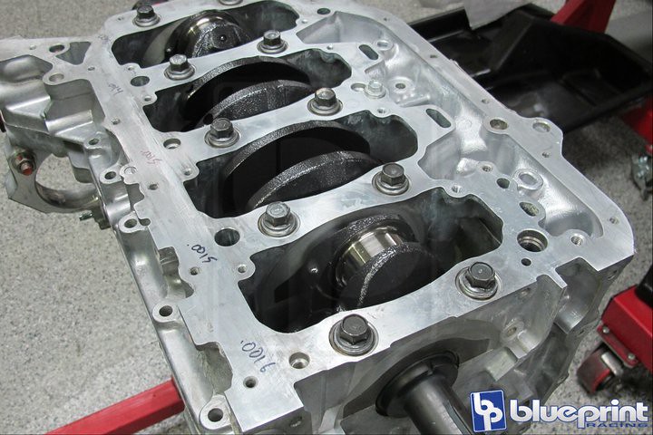
Magnafluxed, Lightened, Straightened, Chamfered, Balanced, Micro-Polished, and Teflon Coated crankshaft installed using Genuine Honda Bearings.
Clearances are measured in a very specific manner… Just know that we do NOT use the block code or plastigage method and we do NOT use ACL unless the customer absolutely insists.
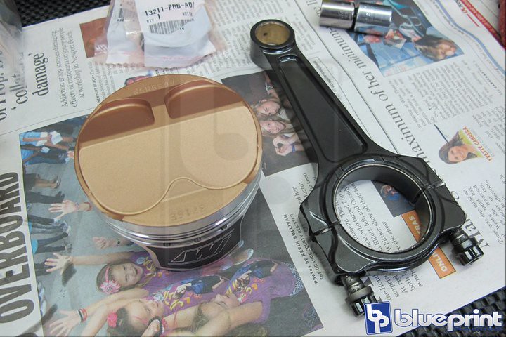
Wiseco “shelf stock” 89mm 12.4:1 slugs that have been treated to Thermal Barrier Dome Coating and Teflon Coated Underside.
We had BP Pro I-Beams listed on the estimate but by the time we got around to pulling parts off the shelf… we realized we were out! Customer dug a little deeper and opted for an even stronger (but heavier) Manley A-Beam.
The rods are overkill but this customer is a firm believer in doing things once! Not wanting to break trend… he opted to have the same Teflon Coating applied to the rods as he did to the other rotating assy. parts
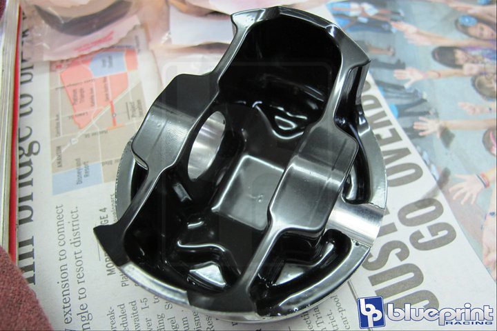
Here you see the Teflon Coated Underside. All moving parts were balanced from the factory but were also balanced as an assembly; a step many customers have us remove to save money.
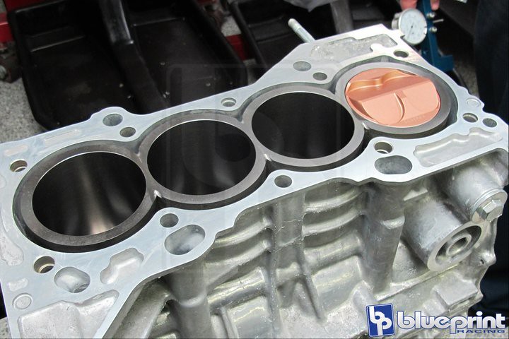
Short Block assembled with one rod and piston, the rod and piston used were assigned to that crank journal and cylinder bore, so we can measure piston volume. We only install one combo because there is a chance we may need to tare it down if we don’t like the numbers we get.
Time is money and we don’t like wasting either…

Here the engine is being rotated manually to find true TDC. Once TDC is realized… the dial is zero’d out and we rotate the the assembly until the piston is exactly 1″ in the hole.
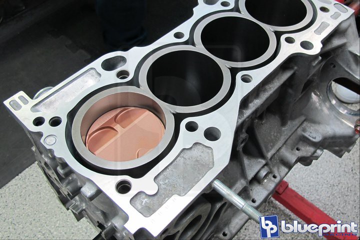
You set the piston in the hole because you cannot measure volume with a dome. The process is commonly referred to as a 1 Down.
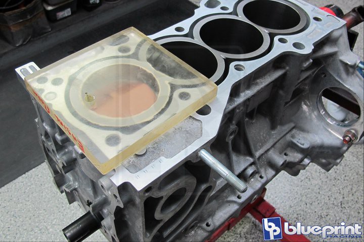
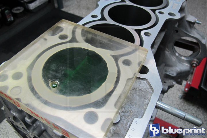
This is the acrylic plate that covers the bore and is sealed with a light coat of white lithium grease. The same grease is used to seal the piston in it’s bore, so the fluid used to cc the block does not pass the rings.
The small hole in the acrylic plate is where the solution will enter the chamber.
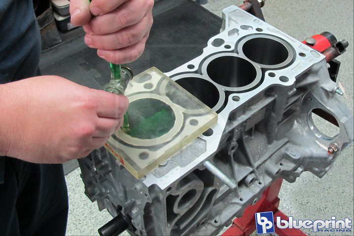
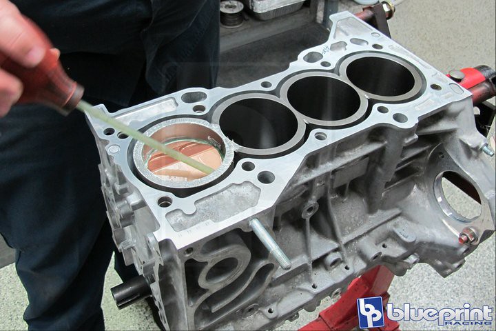
A mixture of 70% isopropyl alcohol and green food coloring (your choice)… is drawn into the cylinder until…
until… all bubbles are gone but just prior to the fluid level coming up and out of the feed hole.
The volume of fluid remaining in the burette is subtracted from the total number you started with… the delta is your volume.
Because “green” 70% isopropyl alcohol is so rare we try to suck as much up as we can so it can grow up and do big things in life. Don’t use your wife’s turkey baster… it didn’t go over well with mine!

Rotate the motor so that the piston moves down and away from the grease so that you may clean up the mess easily.
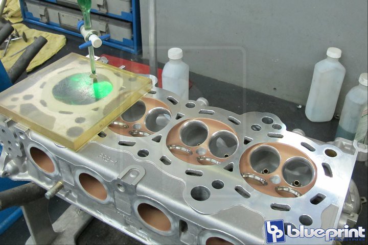
The process is basically repeated in the matching combustion chamber, after all cylinder head work has been performed, to get a final combustion chamber volume.
This will have been the second time we have performed this process; the first time was during/ after chamber work (if the package included it) so we know that the volume of each chamber is the same after massaging.
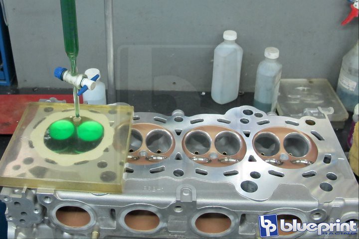
The same math is applied here… record the volume of liquid used so you can calculate later.
The last step is to take the head gaskets thickness and bore and calculate it’s volume. The three volumes and a formula will give you your ACTUAL compression.
This motor was using Wiseco K650M89’s which are advertised to be 14.2:1 but the block was decked, the bore changed, the chambers were massaged, the head was milled, a valve job was performed, and flat valves were used.
This motor produced a CR of 12.55:1 w/ a .027″ gasket
Note: If you think you are going to get what the piston manufacture lists… you have another thing coming to you!
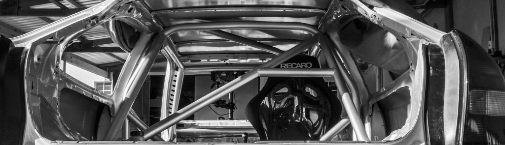
While this was going on, Jerry got back the car from bodywork and paint…
We’ll close out today with one last shot after Jerry got back the car. Here you guys can get a look at how it’s all coming together with the new wheels fitted. Jerry went with a set of Enkei RPF1 17×9.5 +18 at the front and 17×9 +25 at the back, all wrapped in Hoosier A6 rubber 245 40 and 225 45 respectively.
I hope you guys enjoyed the level of information that was provided in this post. Shout out the the guys over at Blueprint Racing for doing an awesome job in documenting this build. Thanks for looking and stay tuned for our next post where we’ll show you the remainder of the build…

Reblogged this on KlanHonda.
Pingback: Track Bred EG6 Build… Part 4 | TDSAutoMag
Pingback: Track Bred EG6 Build… Part 6 | TDSAutoMag
Pingback: Track Bred EG6 Build… Part 9 | TDSAutoMag
I’m impressed by Blueprint Racing’s meticulous attention to detail during their engine building processes.