Jin’s Charmant Build… Introduction
I thought I would do something a bit different, so today we’ll be taking a look at a Daihatsu. All of the builds on this site so far are performance based, and this one will be no different. Some of you who are reading this are probably wondering how can Daihatsu and performance be spoken in the same sentence. First off why would someone put their money, time or effort into making that a reality; when they can just devote it into something of greater worth. Secondly the mere fact that the company never produced anything of high performance should be confirmation.
In recent times a vast amount of builds lean towards the forced induction route, as the culture has gravitated towards a more drag oriented approach especially in the RWD arena. It seems as though, gone are the days when guys built a RWD car for more than solely driving it in a straight line but more for the passion of what a RWD car represents.
Which brings me to Jin, and the passion he has developed for the RWD platform over the years. Which eventually led to him taking the leap and having a go at the dream he had building in the back of his mind. Naturally a Daihatsu wasn’t his first choice, Jin was lucky enough to find an AE86 and just before it was time to go collect it, the guy backed out of the deal leaving him to begin another search. As many of you would know the AE86 is rather rare and finding another one would’ve been both difficult and expensive. This is where the Daihatsu Charmant came into play as an alternative. The Charmant and the AE86 share quite a bit of similarities coupled with the fact that they were easier to find and more reasonably priced. With this knowledge, Jin got rid of his car at the time – a 4A-GE 20v swapped AE91 – and went forward with the Charmant project.
After spending some time doing the necessary research and the wrenching to match, in a few months the project was completed and Jin was able achieve the goal he set out.
With that background info, lets move forward with some photos…
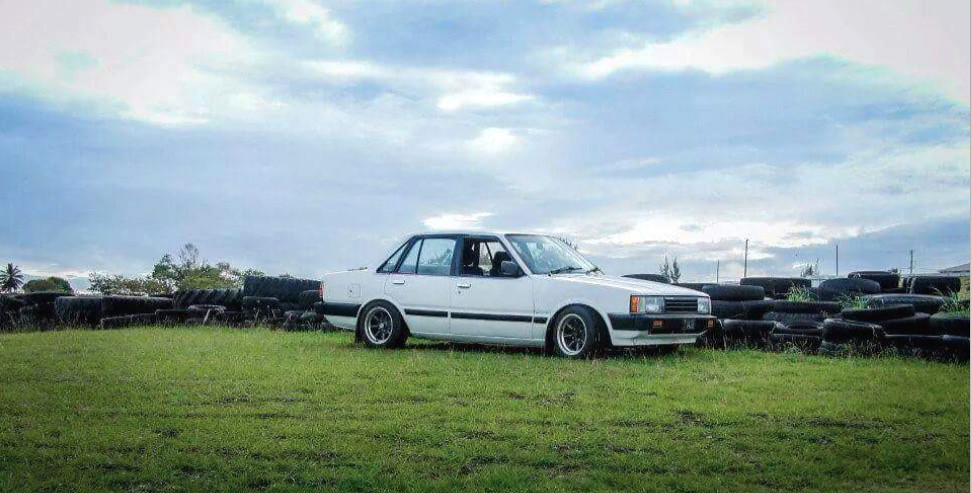
A shot taken at the old Bushy Park Circuit…
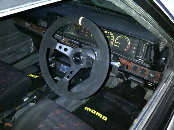
Interior shot…
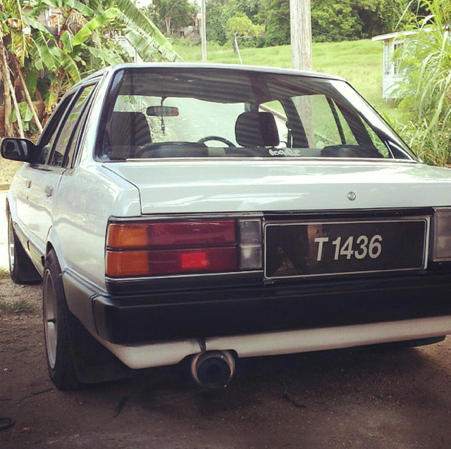
The Charmant has taught Jin many lessons throughout his five years of ownership…
Unfortunately the car was in an accident causing Jin to have to part ways…
A view of the car at the accident scene, where the car was struck from behind…
After closer inspection of the body, Jin knew it wouldn’t make sense trying to have it repaired. In his eyes it was too badly damaged…
A few more shots of the Charmant as it was stripped of what parts were salvageable. Even with his spirit slightly broken, Jin was still determined and went in search of another shell to transfer necessary parts and hopefully improve on his build at the same time…
Close up of one of the original Charmant mudguards which were at all four corners…
Taking a chance to achieve the ultimate balance between acceleration and top end, the car sat on Konig Rewind wheels in a 14 x 7 configuration; wrapped in 185 60 Roadstone N2000 tires. The thick sidewall gave the car the flex needed for cornering and even though the treadwear was low, it provided enough performance for Jin’s application.
Interior partially stripped and being used as temporary storage for some misc parts…
Jin as he works to remove the rear end…
Rear end dropped finally; Jin swapped out the standard Charmant rear end for a Carina replacement complete with a Kaaz 2 way LSD and a 4.7 final drive which in his opinion was the ideal match for his swap.
The shell as it sat stripped after Jin removed all of the salvageable parts…
Adjustable rose jointed Panhard rod that was removed…
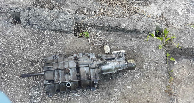
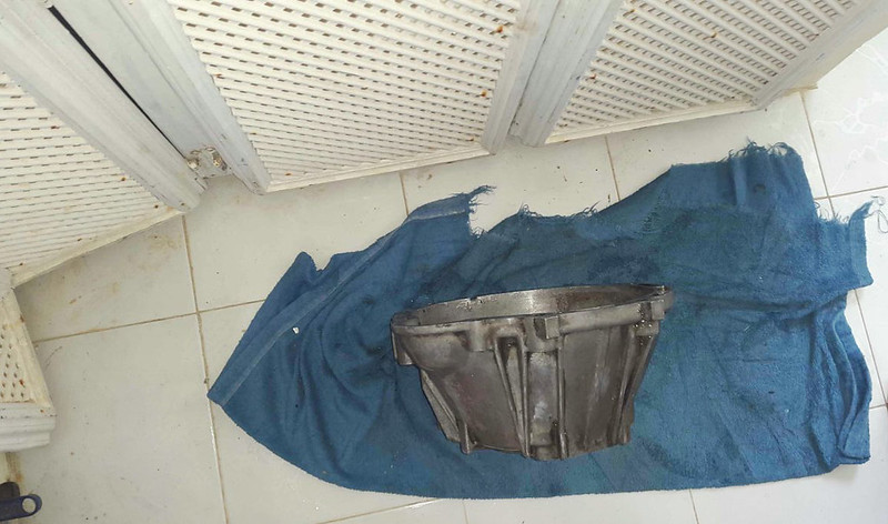
T50 gearbox and bell housing…
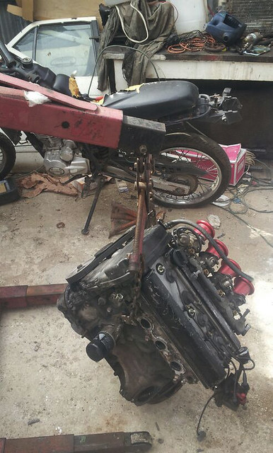
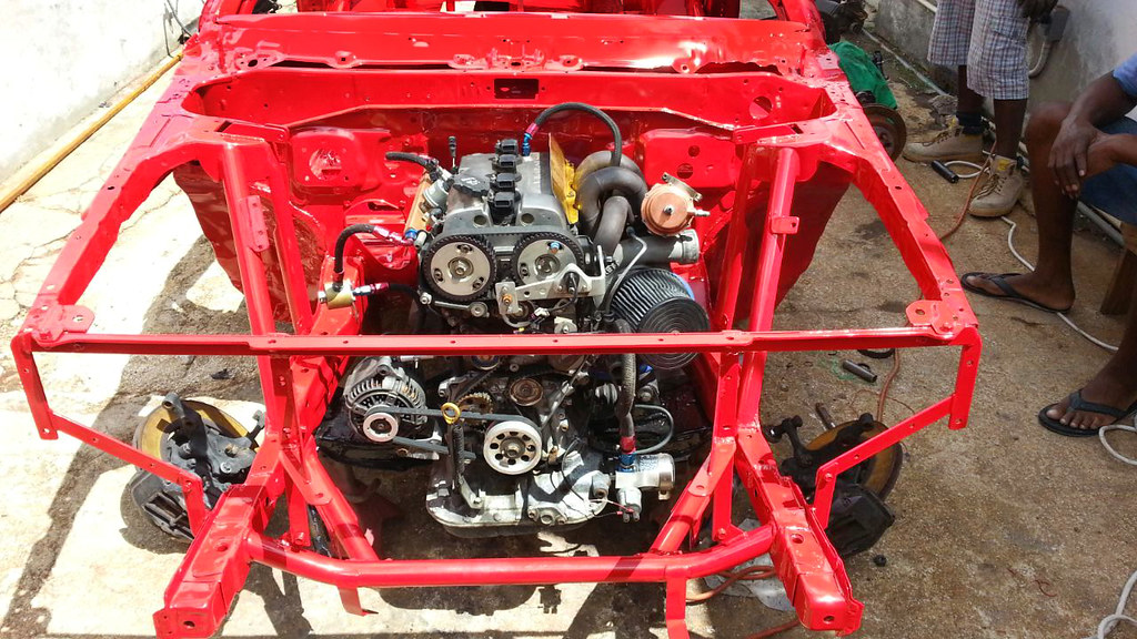
The centerpiece of this project was none other than a 4A-GE 20v motor. Aside from being a fan of the 20v motor, Jin had several other reasons as to why he went with it. Jin had a plan in mind to build a car that would be, in his eyes the ultimate street package with the ability to drag, drift and be taken for the occasional spirited drive. The 20v motor seemed like the perfect match for being competitive, with an output of 160hp being placed in a shell that weighs roughly 900kg.
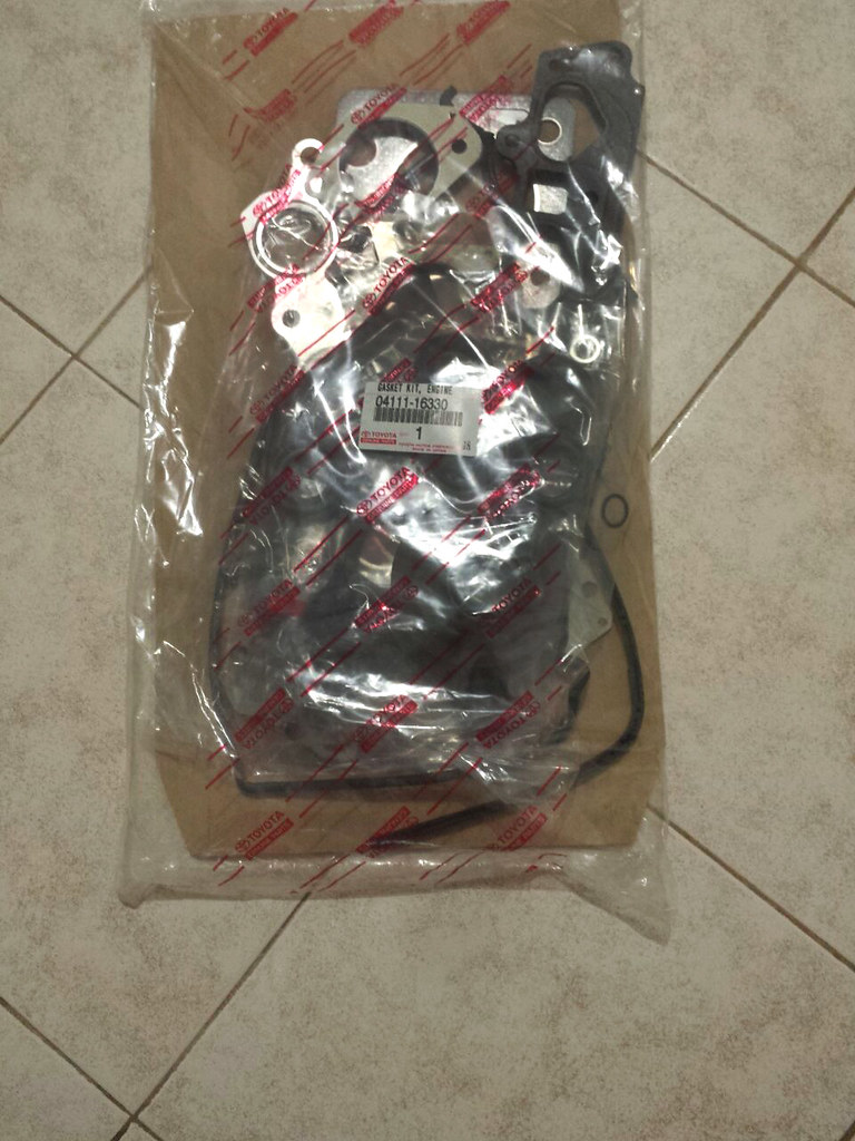
After 5 years of abuse, Jin thought it would be a great idea to have the motor refreshed for a new start…
Jin was able to find a shell and began to work on having it ready by the time the motor would be finished…
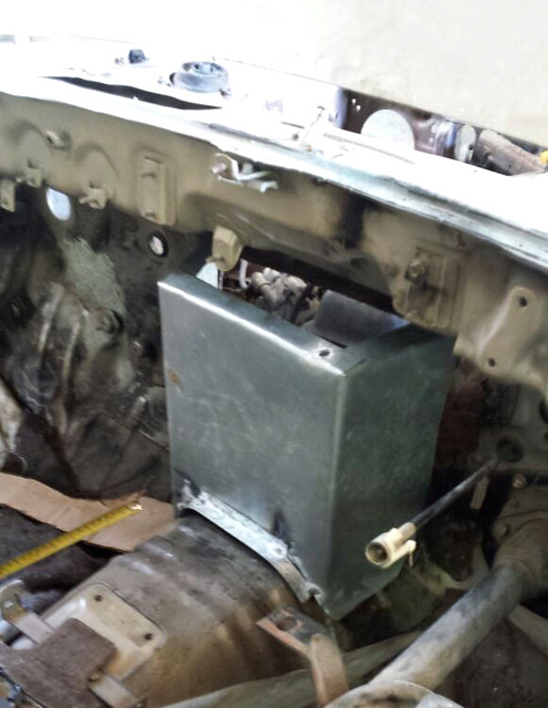
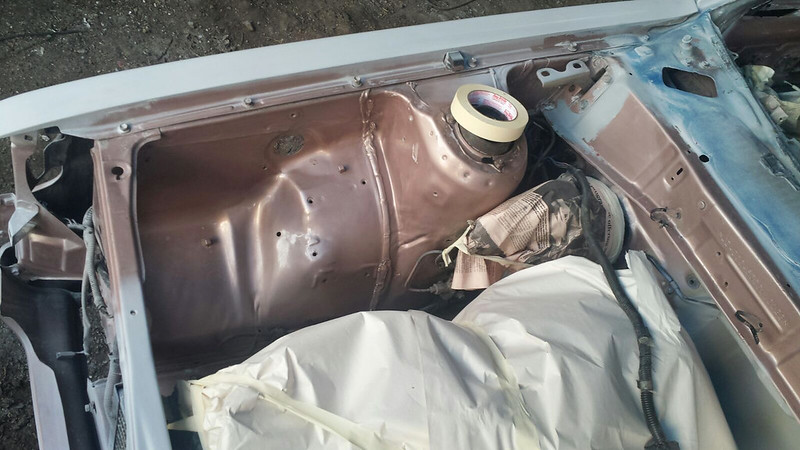
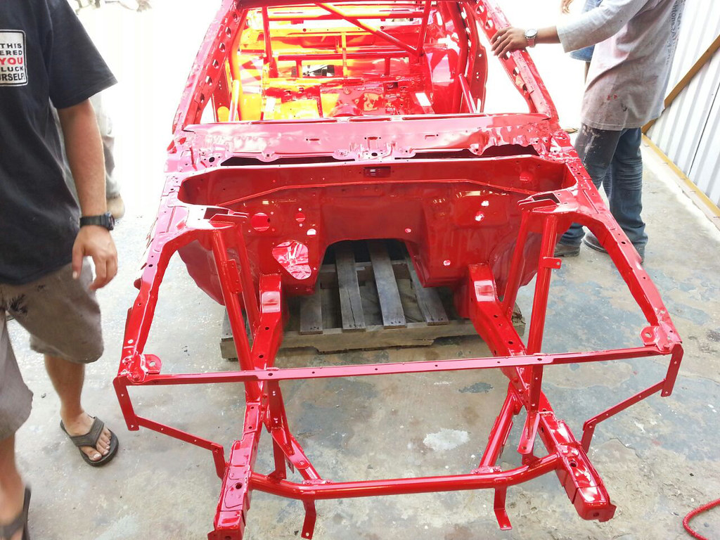
With the shell in his possession, Jin sent it off for the work to begin immediately. One of the more serious modifications which needed to be made was the cutting of the firewall to accommodate the engine.
There were options out there where the firewall was not needed to be cut, but it would have been significantly more expensive and being by Jin was on a tight budget he opted to go the inexpensive route.
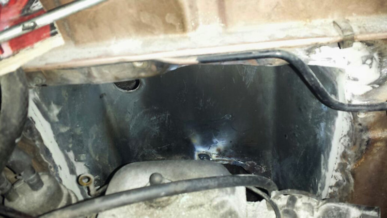
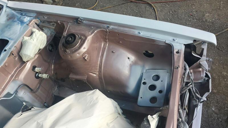
A few photos of the fabrication completed…
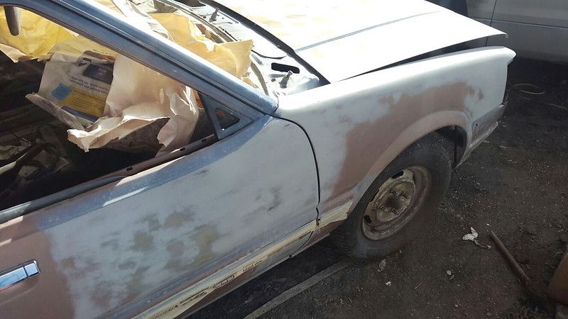
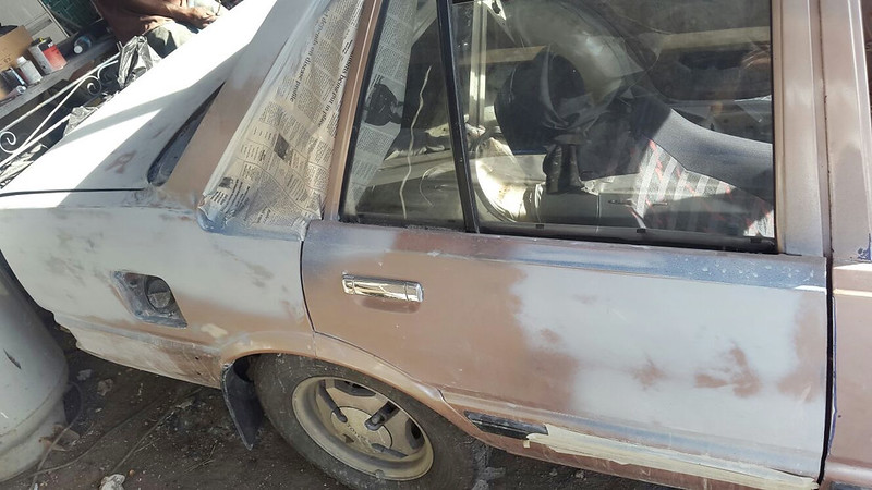
While the firewall was being fabricated, Jin also dealt with a few areas on the body which needed some attention. After all, it was manufactured almost 30 years ago…
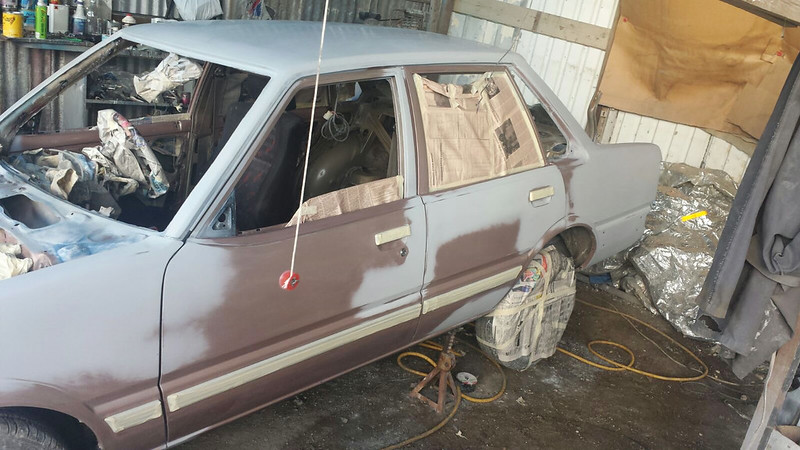
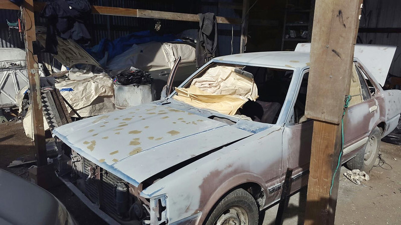
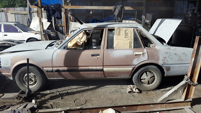
How the car sat, partially disassembled; it still has to be sent over to the paint shop so it made no sense to fully reassemble it…
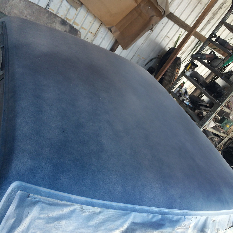
One of the trouble areas was where the roof met the front windshield…
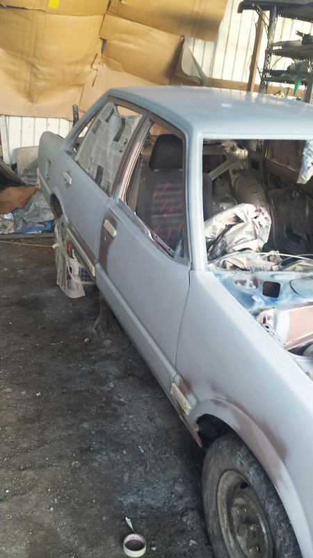
The doors on this car stood up pretty good given its age…
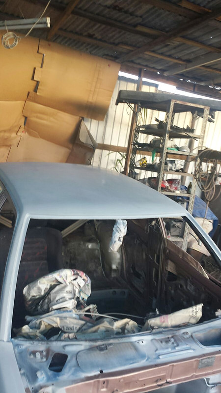
The dashboard needed to be removed to conduct the work done to the firewall and has not been reinstalled as yet…
Throughout the car you can find misc pieces which needed to be cleaned up…
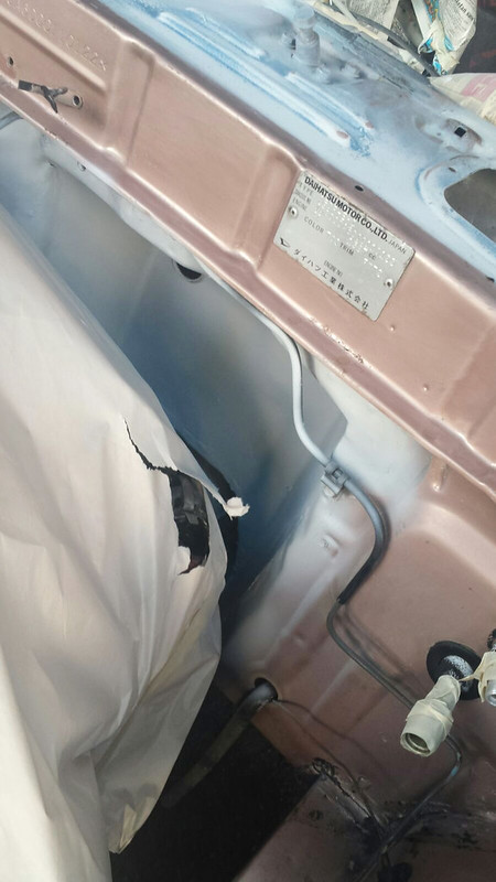
The base of the rear windshield to the right hand side was another area which needed some attention…
The trunk also was filled with misc interior pieces for the reassembly…
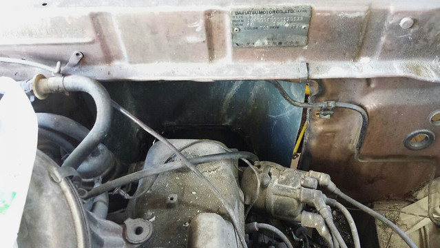
In the engine bay sat a 4A motor and transmission which was surprisingly still in working condition…
A view from the other side…
There was something however that didn’t quite stand up to the test of time, the door panels….
Jin bought some wood to replace the previously used cardboard; once the wood was cut into shape the plan was to have them upholstered…
A look at the partially completed product…
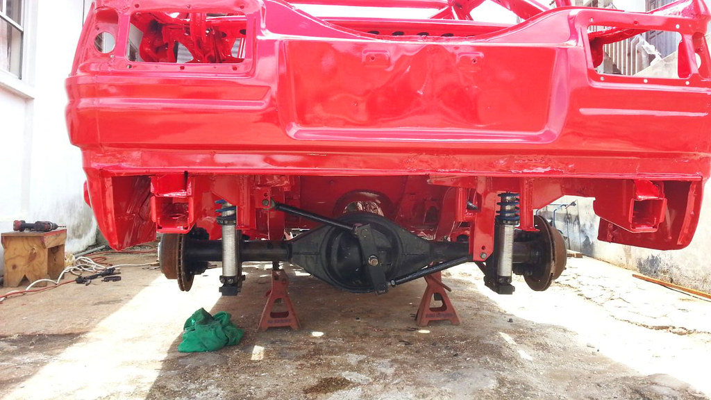
Rear drum brakes received a fresh coat of paint…
Going up with this new project, Jin plans on using AE86 slotted and drilled rotors with AE100 calipers…
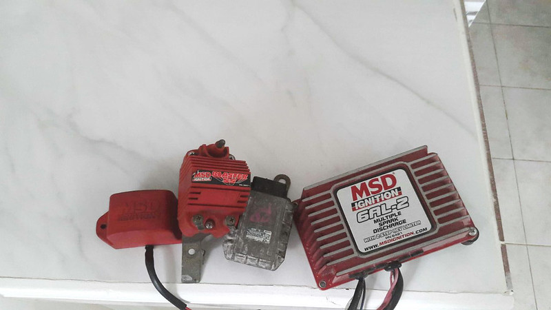
MSD ignition system that will be used…
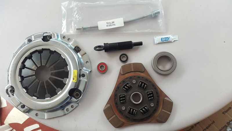
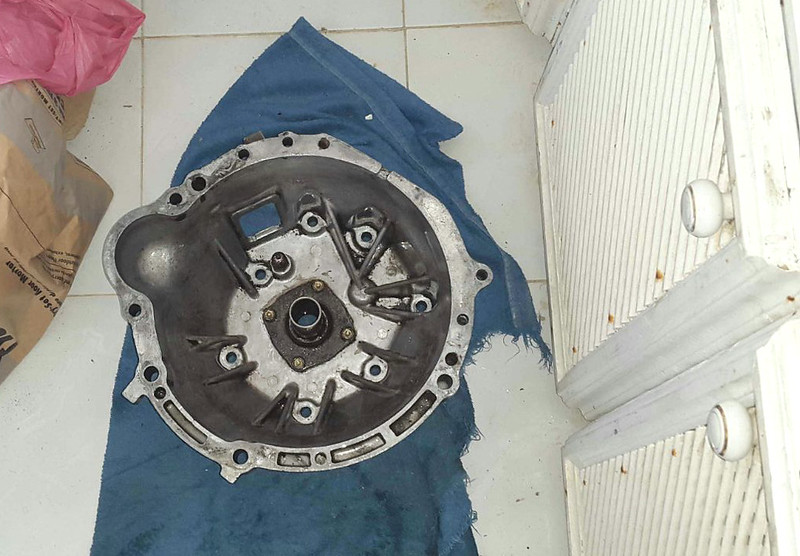
Exedy stage 2 clutch kit…
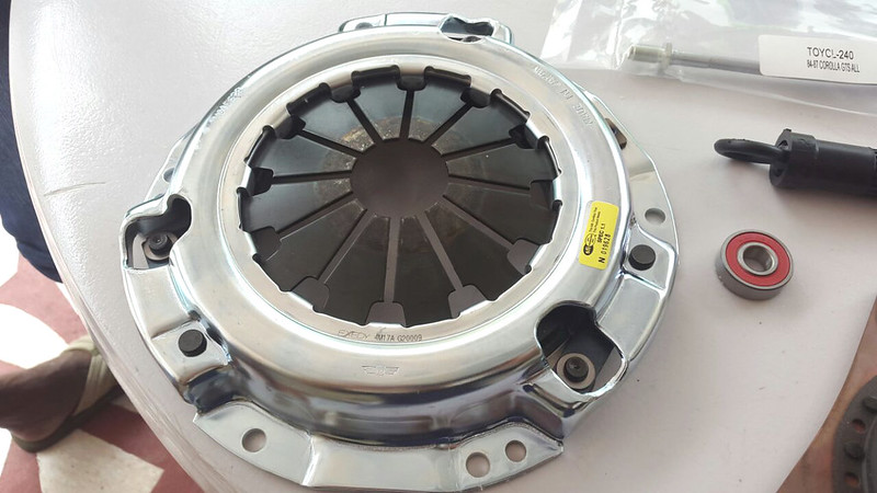
Consisting of a heavy duty pressure plate…
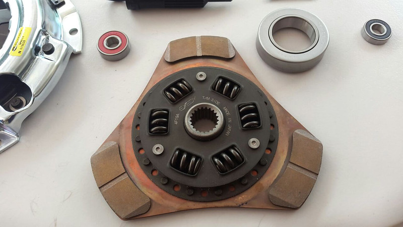
And a 3 puck, spring hub copper clutch disc…
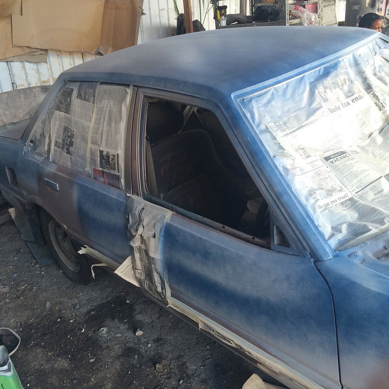
Meanwhile, the car was sent over to the paint shop…
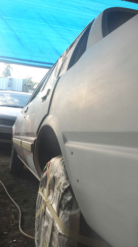
Where the priming and sanding began…
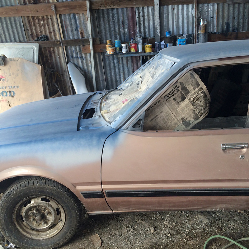
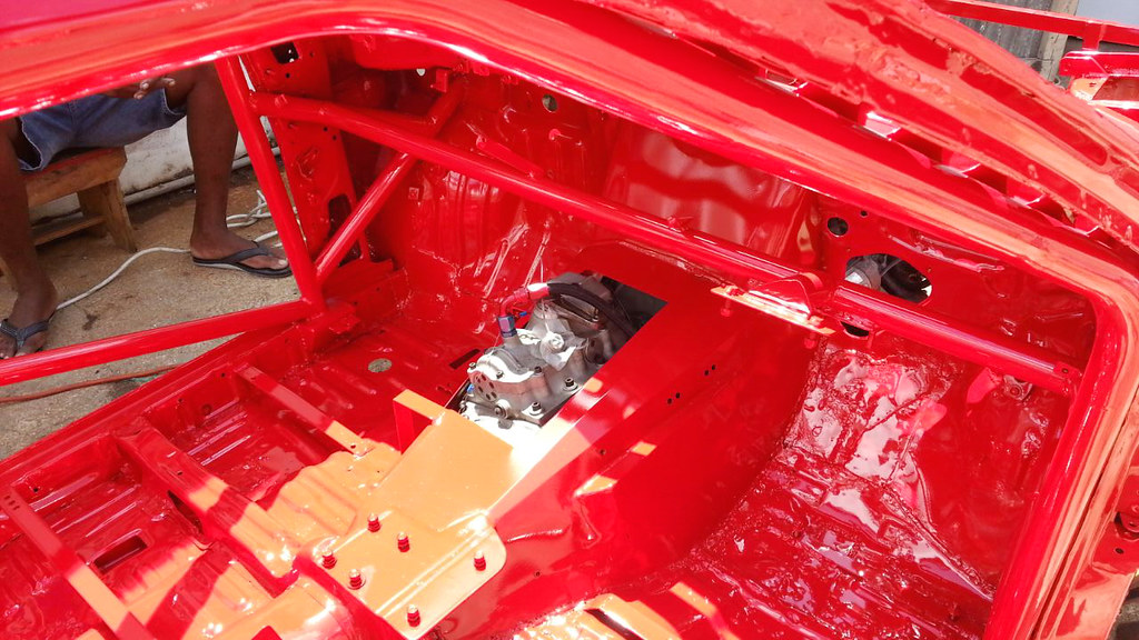
Engine bay masked, primed and ready for some paint…
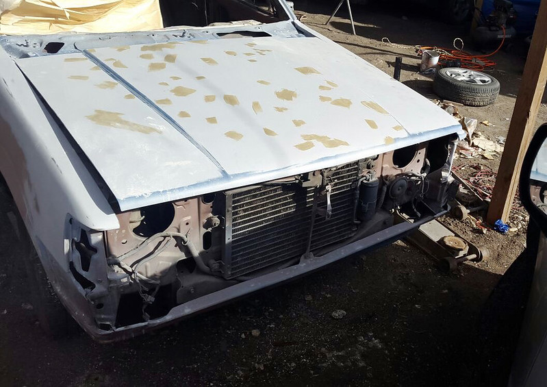
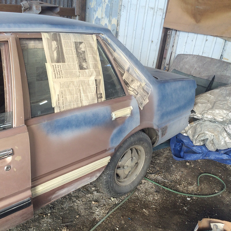
Few more shots of the process the car went through…
Before starting the paint process…
The next phase from here is to have the final paint applied. Which brings us to the end of today’s post, I hope you guys enjoyed a first look at Jin’s Charmant build. Thanks for taking a look and stay tuned for more to come…
Boosted AE86 Monster… Part 1
After the last post we have learnt that Corey is not the conventional thinker and likes to explore all of his options and then some. I gave you a first look at his build along with a fresh shell that will be used to transfer practically everything onto. Before this could be done, Corey needed to first put the shell under the knife for some major modifications. Being by Corey does all the work himself, there was no time wasted and work started immediately. Today we’ll be taking a look at the progress Corey has made with the shell.
For those of you who would have missed the first post and would like a recap, I’ve provided the link below…
Boosted AE86 Moster… Introduction
In a matter of days Corey had the majority of remaining works almost completed…
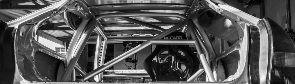
From the outside looking in at the roll cage and the gutted interior…
Markings on the roof, outlining where it will be cut and replaced with a lighter fiberglass piece…
An over looked area on Corey’s previous build were the rear wheel wells. This time around Corey made sure they were a priority. With the old build, the car’s purpose evolved over time after switching between being a street car to a part drag car, part track day car until becoming a more drag focused vehicle. Because of this evolution, there were some areas which wouldn’t have been resolved unless the car was stripped down. Corey made sure the rear wheel wells were tubbed with enough clearance to run a tire that will provide the traction needed to get the car down the straight.
A closer look at the work done to the arches; with this change Corey will be able to run a 28″ tire which is a big step up from the previously used 26″ tires.
With a build of this caliber a welded cage was of high importance not only for safety but also for some additional rigidity…
The main hoop of the roll cage gusseted to the body of the car…
A view towards the back, where you can see the tubbed wheel arches and modified tunnel to give enough clearance on the initial launch for the 9″ rear end.
The roll cage is tied into both shock towers and the two towers are connected by a piece of pipe that on either side, provide additional stability for the Stanford Industries watts linkage.
The reengineered rear of the car where you get a better view of the tunnel…
To help improve his launch, Corey opted go with a 4 link suspension setup…
The parallel 4 link is designed to keep the rear axle centered, and to keep the pinion angle from changing (keep the axle from rotating). It works especially well under hard acceleration at the drags or hard cornering at the track. For drag purposes it has an adjustable anti-squat geometry to aid with launching the car as efficiently as possible.
Closer look at the modification made to the rear of the car to house the Stanford Industries 4 link suspension…
A look at the rear portion of the roll cage and the underside of the roof skin that will soon be replaced…
Working our way to the front end, which also saw some heavy modifications…
The factory tunnel and a portion of the firewall was cut away and replaced with a custom fabricated aluminum tunnel. As you can see it is significantly wider to accommodate the large Saenz TT3 sequential gearbox and 3S motor.

Corey has plans on using full race bucket seats which require custom mounting points for them to be properly aligned with the Tilton pedal box…
An additional portion of the firewall where it meets with the wheel well was removed and a custom piece welded in place to allow for more wheel clearance…

An electronic steering setup will be used just like quite a few builds on this site. Corey will be using a modified Opel Corsa unit…
How the roll cage is tied to the base of the floor and the connection to the shock tower and dashboard support…

Looking from the outside towards the back of the car showing the roll cage gusseted to the A pillars…
At the front there isn’t much, apart from the chassis and some additional piping…
The gutted front end, the purpose of this design was to save weight where he could while making it easy to get work done within the engine bay…
A look at the minimalist radiator support design…
Shedding weight where possible was upmost important to Corey but he also wanted to retain the standard suspension points. After calculating what should go, Corey reinforced the shock towers and tied them directly into the chassis…
Semi aerial view of the front end just before the shell was sent to Bishtons Sandblasting…
Over at Bishtons’ the guys sandblasted the shell as to get a clean base before powder coating it in this vibrant red similar to the one on his previous shell…
In the booth, just after it was completed and ready to be collected…
Loaded up and ready to make the trip home…
Finally at home just before the work begins…
Rear end complete with brakes, coilovers and the Stanford Industries Watts linkage installed…
A Watts linkage is used as an improvement over the Panhard bar. Both methods intend to prevent relative sideways motion between the axle and body of the car. Watts linkage approximates axle movement in a vertical straight line motion more closely, and does so while locating at the center of the axle rather than toward one side of the vehicle, as more commonly used when fitting a long Panhard rod. By locating the center of the axle the roll center of the vehicle can be clearly defined and thus be predictable and completely tuneable.
With the diff and suspension components in place at the rear, the engine and gearbox were quickly bolted into the engine bay.
That brings us to the end of today’s post, thanks for taking a look and stay tuned for more the come on this build.
