Boosted AE86 Monster… Part 1
After the last post we have learnt that Corey is not the conventional thinker and likes to explore all of his options and then some. I gave you a first look at his build along with a fresh shell that will be used to transfer practically everything onto. Before this could be done, Corey needed to first put the shell under the knife for some major modifications. Being by Corey does all the work himself, there was no time wasted and work started immediately. Today we’ll be taking a look at the progress Corey has made with the shell.
For those of you who would have missed the first post and would like a recap, I’ve provided the link below…
Boosted AE86 Moster… Introduction
In a matter of days Corey had the majority of remaining works almost completed…
From the outside looking in at the roll cage and the gutted interior…
Markings on the roof, outlining where it will be cut and replaced with a lighter fiberglass piece…
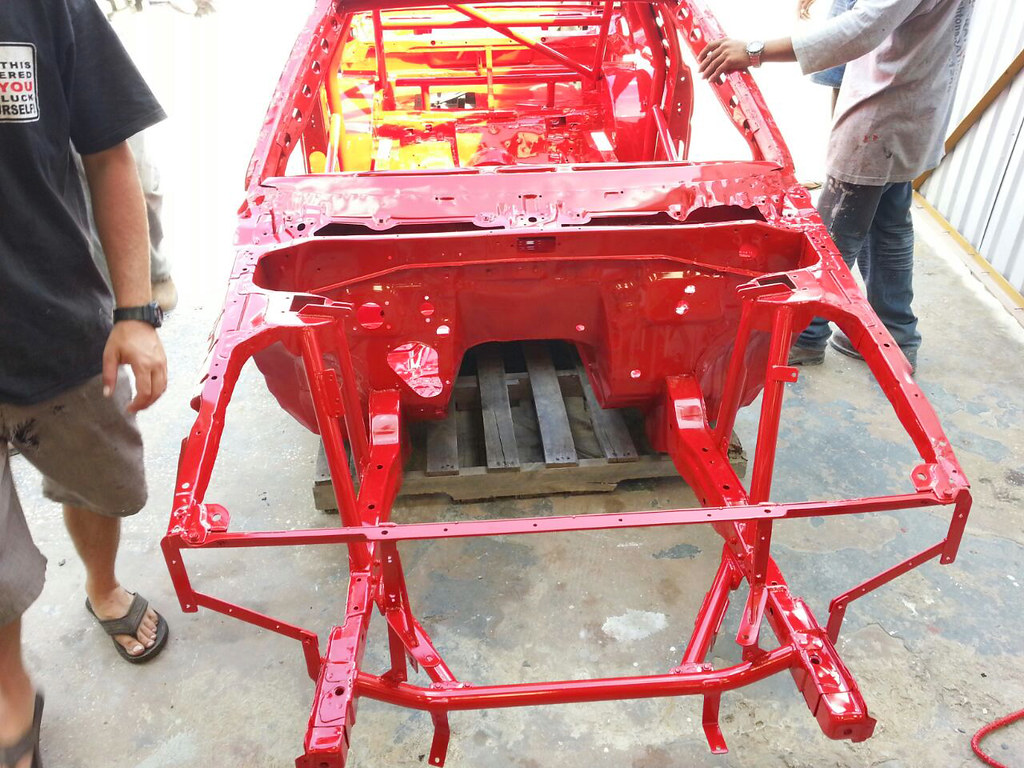
An over looked area on Corey’s previous build were the rear wheel wells. This time around Corey made sure they were a priority. With the old build, the car’s purpose evolved over time after switching between being a street car to a part drag car, part track day car until becoming a more drag focused vehicle. Because of this evolution, there were some areas which wouldn’t have been resolved unless the car was stripped down. Corey made sure the rear wheel wells were tubbed with enough clearance to run a tire that will provide the traction needed to get the car down the straight.
A closer look at the work done to the arches; with this change Corey will be able to run a 28″ tire which is a big step up from the previously used 26″ tires.
With a build of this caliber a welded cage was of high importance not only for safety but also for some additional rigidity…
The main hoop of the roll cage gusseted to the body of the car…
A view towards the back, where you can see the tubbed wheel arches and modified tunnel to give enough clearance on the initial launch for the 9″ rear end.
The roll cage is tied into both shock towers and the two towers are connected by a piece of pipe that on either side, provide additional stability for the Stanford Industries watts linkage.
The reengineered rear of the car where you get a better view of the tunnel…
To help improve his launch, Corey opted go with a 4 link suspension setup…
The parallel 4 link is designed to keep the rear axle centered, and to keep the pinion angle from changing (keep the axle from rotating). It works especially well under hard acceleration at the drags or hard cornering at the track. For drag purposes it has an adjustable anti-squat geometry to aid with launching the car as efficiently as possible.
Closer look at the modification made to the rear of the car to house the Stanford Industries 4 link suspension…
A look at the rear portion of the roll cage and the underside of the roof skin that will soon be replaced…
Working our way to the front end, which also saw some heavy modifications…
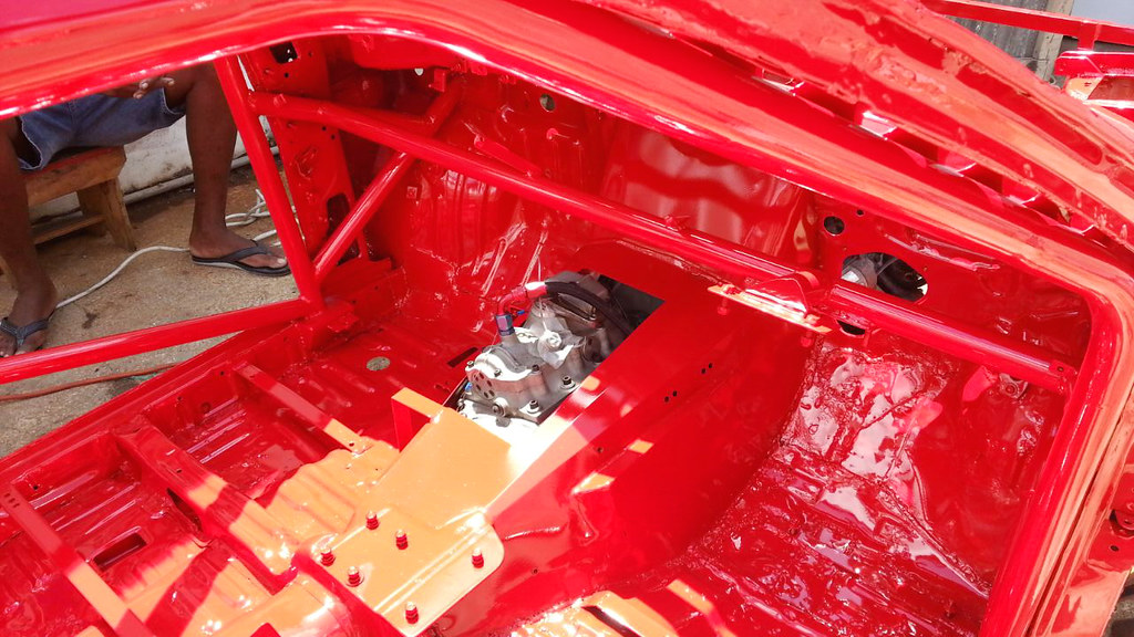
The factory tunnel and a portion of the firewall was cut away and replaced with a custom fabricated aluminum tunnel. As you can see it is significantly wider to accommodate the large Saenz TT3 sequential gearbox and 3S motor.

Corey has plans on using full race bucket seats which require custom mounting points for them to be properly aligned with the Tilton pedal box…
An additional portion of the firewall where it meets with the wheel well was removed and a custom piece welded in place to allow for more wheel clearance…

An electronic steering setup will be used just like quite a few builds on this site. Corey will be using a modified Opel Corsa unit…
How the roll cage is tied to the base of the floor and the connection to the shock tower and dashboard support…

Looking from the outside towards the back of the car showing the roll cage gusseted to the A pillars…
At the front there isn’t much, apart from the chassis and some additional piping…
The gutted front end, the purpose of this design was to save weight where he could while making it easy to get work done within the engine bay…
A look at the minimalist radiator support design…
Shedding weight where possible was upmost important to Corey but he also wanted to retain the standard suspension points. After calculating what should go, Corey reinforced the shock towers and tied them directly into the chassis…
Semi aerial view of the front end just before the shell was sent to Bishtons Sandblasting…
Over at Bishtons’ the guys sandblasted the shell as to get a clean base before powder coating it in this vibrant red similar to the one on his previous shell…
In the booth, just after it was completed and ready to be collected…
Loaded up and ready to make the trip home…
Finally at home just before the work begins…
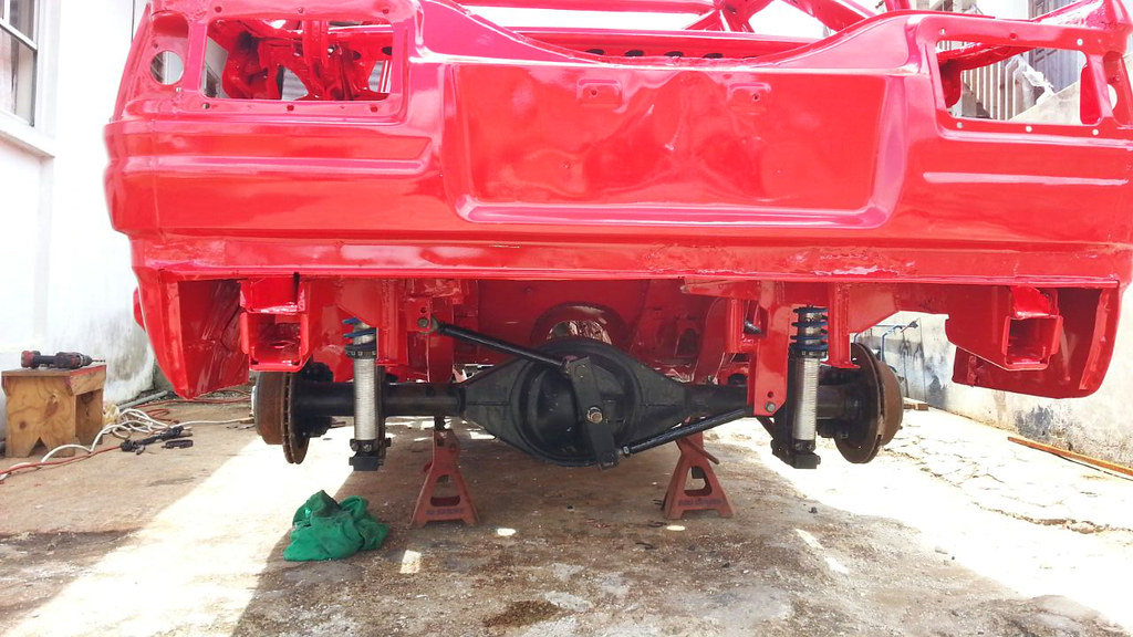
Rear end complete with brakes, coilovers and the Stanford Industries Watts linkage installed…
A Watts linkage is used as an improvement over the Panhard bar. Both methods intend to prevent relative sideways motion between the axle and body of the car. Watts linkage approximates axle movement in a vertical straight line motion more closely, and does so while locating at the center of the axle rather than toward one side of the vehicle, as more commonly used when fitting a long Panhard rod. By locating the center of the axle the roll center of the vehicle can be clearly defined and thus be predictable and completely tuneable.
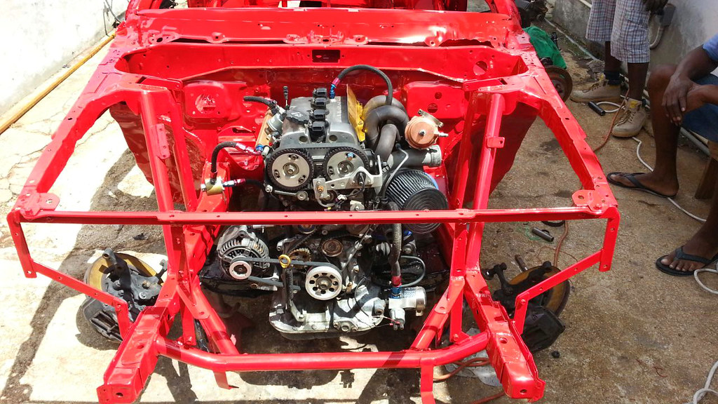
With the diff and suspension components in place at the rear, the engine and gearbox were quickly bolted into the engine bay.
That brings us to the end of today’s post, thanks for taking a look and stay tuned for more the come on this build.
